F4LW Software
The entire F4LW code is open source, you can use it for your personal projects and enjoyment, but commercial use without my permission is prohibited.
PIC code
The MCU used is a PIC 16F648A, which is almost the same chip as the better known 16F628, but contains 4k flash instead of 2k, about 3.5k flash are currently in use. The MCU runs at 4 MHz (internal oscillator).
The code is written entirely in assembler and is my original design. I used MPLAB 7.20 to develop it and the PICKit 2 ICSP programmer to burn the flash.
By setting the symbol GERMAN to 0 or 1 in the assembler
command line, you determine, if the English or the German version is built.
They differ by:
- Names of days of week
- Font included (brackets and braces vs. umlauts)
- Minor differences in message edit mode
Generally, the English code works with a German EEPROM word list and vice versa. Only the umlauts/braces will look strange.
Main loop and state machine
A finite automaton of 22 states (see STATE_* in
f4lw.asm) is employed to control the overall operation
of the F4LW. Some states are persistent (stored in NV RAM), while
others are
temporary (like the "download" or "show" states). State transitions
are either synchronous with the (endless) main loop, these are triggered
by the remote control buttons or the hardware button, other transitions
are asynchronous, triggered by interrupts, e.g., download finished, goto
saving state. Saving can't be handled in interrupt for two reasons:
- Saving may take some time which would cause display flicker, since nested interrupts aren't possible with PICs.
- The call nesting limit (8 levels) might be exceeded
The time for one pass through the main loop is normally 0.1s (by an explicit delay loop), but may be shorter (for animations) or longer (power-up display) for some states. The remote control input is tested at the end of each main loop pass.
Multiplexing the display
The hardware aspect of multiplexing is described here. Timer2 of the PIC is used as the interrupt source to update the tube display. Each tube in turn is switched on and off; by varying the duty cycle length brightness can be controlled.
I2C bus emulation
The 16F648A doesn't have I2C hardware, so the bus is emulated
in software. To avoid frequent register page changes (once per bit
transmitted!), I used the 3-pin routines by François Gerin, defined
in I2C_M_3pins.asm
PIC internal eeprom
The PIC internal EEPROM is read only, containing fixed display texts and bit mask patterns for character animation.
Random number generation
Random numbers are generated using a linear feedback shift register (LFSR) with 47 bit length. It uses only 8 bytes of RAM and only 20 program steps, but has a cycle length of 247-1 bits, so it takes 557 years until the sequence of random numbers repeats, assuming generating 1000 randoms per second.
It's not cryptographically safe, but it's good enough for generating random words. The LFSR is initialized from the real-time clock at program start.
Decoding RC-5 remote control codes
The TSOP1736 IR receiver output is connected to RB5 which triggers an interrupt on level change. Now timer 0 is reset and the handler is finished. At the next edge interrupt the timer value is read and compared to a threshold to determine if it was a short or long pulse. Spikes (very short pulses) and timer 0 overflows (too long pulses) indicate errors and reset the receiver state machine. When enough pulses have been accumulated, the RC-5 code and the toggle bit (used to distinguish long button press from repeated press of the same button) are extracted and stored in RAM locations where the main loop interprets them.
Long button presses (auto-repeating) are only recognized for the speed and brightness buttons (and the Cursor up/down buttons in Message Edit mode).
The RC-5 group code is currently ignored, the F4LW responds to any group code.
Clock operation
The PIC has no internal representation of the current time and date, instead on each display update (every second or when selecting another clock display mode) time and date are read from the DS1307 real-time clock chip via the I2C bus. This is fast enough and saves a lot of program space.
The clock chip is programmed to output a 1Hz signal which is connected to the interrupt pin (RB0) of the PIC. However, the interrupt itself is never triggered, but the F4LW simply polls RB0 in clock mode. The interrupt might be enabled in future versions, but currently this is not necessary.
The RTC chip also contains 56 bytes of battery buffered RAM, which comes handy to store parameters frequently changing (so writing them to EEPROM could exceed the maximum write cycles) but which should/must be retained while power is off. Parameter stored in NV RAM include display mode, options, speed, brightness, and last but not least the 10 user-defined messages.
Accuracy of sun and moon
The moon phase calculation assumes a synodical moon of 29½ days (like most wrist-watches), so it will be off by one day in three years. However, whenever you set the clock, the difference between the exact lunar phase and the F4LW approximation is calculated and a gauge register in the F4LW is set.
Sunrise and set times are not at all calculated by the F4LW's PIC (these calculations are much too complicated for this simple chip), but are precomputed for each day of the entire year on the PC and stored to the top 1.5 kB of EEPROM when you set the clock. They are typically accurate to 1-2 minutes. Though these times are calculated for the current year when setting the clock, they are accurate enough for subsequent years, too.
Generating word chains
Two of the word generation schemes (selecting random word from dictionary and selecting independant random letters) are trivial, but the third one (building word chains) is a bit tricky. Unlike the Python version, the PIC is too slow to search the dictionary for successor words, so tables have been precomputed containing lists of potential successors.
The algorithms tries to avoid a word which has been displayed 1 step before and so the graph traversal may lead into a dead end. In this case, **** is displayed and a new starting word is chosen. But there are groups of words not reachable from the majority of the words. When such a group has more than 2 words, the F4LW might not be able to leave it and display the same words forever. So these words have an indicator bit set (precomputed) to allow the F4LW to break randomly out of the group and select a new random starting word.
Terminal mode protocol
The serial interface runs at 19200 baud, 8 bits, no parity. Use a standard (non-crossed) RS232 cable to connect F4LW to your PC/Mac/whatever.
When put into Terminal mode,
the F4LW sends ASCII STX (=0x02) to the RS232,
when leaving Terminal mode it sends ASCII ETX
(=0x03). You should ignore additional STX
when already in Terminal mode and ignore ETX when not
in Terminal mode, since F4LW sends STX whenever the
yellow button is pressed and ETX when another major
mode (or "off") is selected.
Every character received in Terminal mode is shifted into the display
buffer from the right and the leftmost character gets lost. If you want to
change the entire display, you can send 4 characters quickly to shift out
the 4 current ones. The Python program ticker.py reads a
file and displays it on the F4LW in a ticker-like fashion.
F4LW can display all ASCII characters 32-127. The control codes 0-31 are filled with various Greek and symbol characters.
In Terminal mode, buttons pressed on the remote control are converted
to characters according to keymap.inc and sent back to the
PC via RS232. You can use any programming language to communicate with
F4LW, of course, but I recommend
Python, which is
a simple but powerful language allowing fast interactive
program development and experiments.
Python support code
To use this code you need
Python 2.4 and the
pyserial
library. f4lw.py contains the basic RS232 communication
functions used in the command line utilities.
Font creation
Use the Python program b7971viewer.py to display the
F4LW's font on the PC and to create the PIC include files
segments_hi.inc and segments_lo.inc. Simply
edit the bit patterns in the chars dictionary in
b7971font.py to try different font designs.
Creating a lower case font for 14-segment displays is difficult. There are a lot of designs looking quite good alone but which suck in context. I found the most important aspect of font design is keeping the height uniform, so my main objective was to make the ascenders and descenders correct, irregarding the look of a lone character.
The only characters causing problems are lower-case p
and q, where there isn't a satisfactory design for 14 segments
not involving the upper segments.
With B7971toPS.py you can generate
PostScript font charts,
too. (German,
English)
Word list creation
makeROM.py converts a text file containing one word per
line to an EEPROM image to be uploaded to the F4LW with
uploadROM.
words.py contains the code to build word chains,
determine cliques of words reachable (to break cycles),
and finally assemble the EEPROM file for the F4LW.
Command line utilities
These are the programs uploadROM.py,
uploadMessages.py and setclock.py already
mentioned in the User's guide.
F4LW as a terminal
The function sync_server in f4lw.py
handles serial communication and the STX/ETX protocol mentioned
above to easily write synchronous Python server code.
The sample program samplehandler.py shows the
interface. When Terminal mode is started, an instance of the
the class is created, which will be destroyed when exiting
Terminal mode. During its lifetime, the method display
is called, which should return the string to be sent to F4LW, and
input is called when a button on the remote control is
pressed. The class Echo defined here simply echoes the
character received to the F4LW.
The sample program calc.py does a little more: It
implements a simple 5-function pocket calculator (integer only)
in just 70 lines. The keys for +,-,*,/ are the keys in the row above
the colored keys, square root is the AV key, = is the
Enter key, -/-- changes the sign, and
Menu clears the display.
A slightly more complex asynchronous server will be added in the near future.
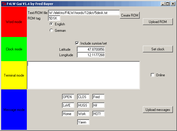
F4LWGui
This is a GUI application combining all upload utilities (and
a very simple terminal program to play with
Terminal mode) in an easy
to use program. Start it with python f4lwGui.pyw.
All values entered are remembered in a configutaion file.

ROM image creation and upload
Double-clicking
the Text/ROM file entryfield opens a file selection dialog. Enter
the ROM tag (4 letters) and press Create ROM to create
a ROM file (with the extension .f4lw), which takes a few
seconds. Be sure to select the right language! Now put F4LW into
Word mode, press the hardware button
and press Upload ROM to transfer the ROM image to the F4LW.
Setting the clock
Put F4LW into Clock mode, press the hardware button, and press Set clock to set F4LW to the computer's current time and date. If you want to create sunrise/set times for your location, check this option and enter your geographic latitude and longitude in the entryfields. (Decimal fraction, positive for east/north, negative for west/south) You have to do this only the first time you set the clock.<
Using the terminal
Put F4LW into Terminal mode and check the Online box. Now every char input into the text area is sent to the F4LW and chars received via the remote control are displayed.
Uploading messages
Put F4LW into Message mode, enter upto 10 messages (4 letters each) into the entryfields, press the hardware button, and press Upload messages. The language setting mentioned above applies here, too.
Download
Now, finally here's the entire code archive, containing all PIC and Python code and also some word lists.